Understanding octg casing and Tubing Pipe Dimensions & specifications: A Comprehensive Guide for Oil and gas professionals
As oil and gas professionals, it is essential to understand the octg casing and tubing pipe dimensions and specifications of the pipes used in the industry. This comprehensive guide will provide you with a detailed overview of the OCTG casing and tubing pipe dimensions and specifications, so you can make informed decisions when selecting the right pipes for your projects.
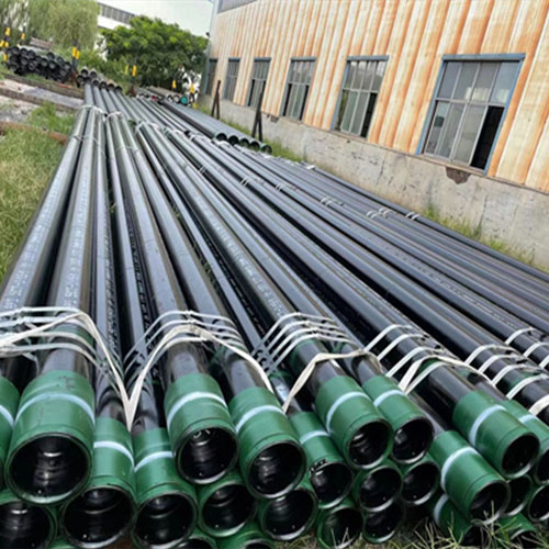
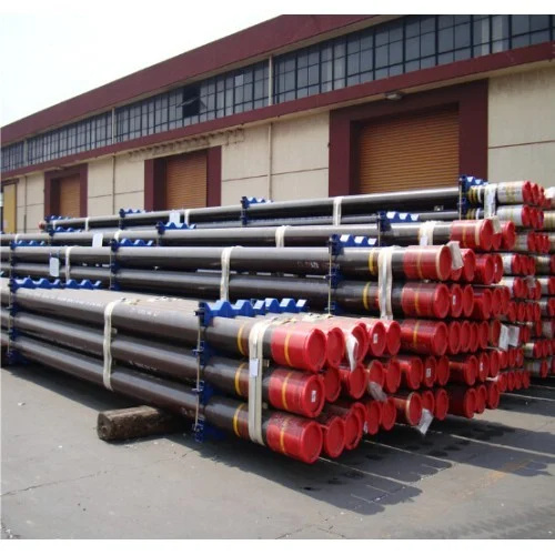
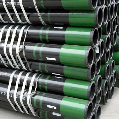
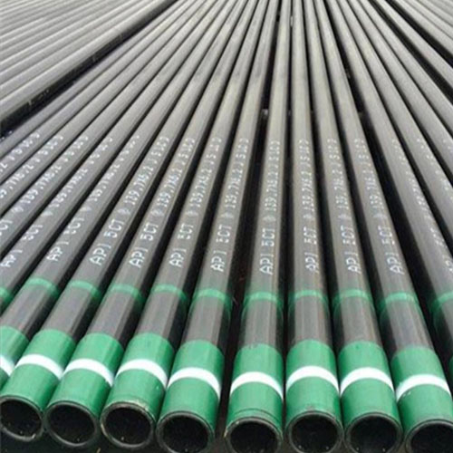
oil tube Chinese high-grade Wholesaler,casing pipe china good Company,The OCTG casing and tubing pipe dimensions and specifications are determined by the American petroleum Institute ( API). The API sets the standards for the size, Wall thickness, Weight, and grade of the pipes used in the oil and gas industry. The API also sets the standards for the Threading, connections, and other features of the pipes.
The OCTG casing and tubing pipe dimensions and specifications are based on the nominal outside Diameter (OD) of the pipe. The nominal OD is the outside diameter of the pipe, measured in inches. The wall thickness of the pipe is determined by the nominal wall thickness (WT), which is measured in inches. The weight of the pipe is determined by the nominal weight (NW), which is measured in pounds per foot. The grade of the pipe is determined by the grade of the material used to make the pipe.
The OCTG casing and tubing pipe dimensions and specifications are also determined by the type of threading used on the pipe. The most common types of threading are the American Petroleum Institute (API) threading, the National Pipe Thread (NPT) threading, and the Buttress threading. The API threading is used for most oil and gas applications, while the NPT threading is used for water and gas applications. The Buttress threading is used for high-pressure applications.
The OCTG casing and tubing pipe dimensions and specifications are also determined by the type of connection used on the pipe. The most common types of connections are the butt-welded connection, the Threaded connection, and the socket-welded connection. The butt-welded connection is used for most oil and gas applications, while the threaded connection is used for water and gas applications. The socket-welded connection is used for high-pressure applications.
| Calculated Mass c | |||||||||||
| Nominal Linear Mass T& C b,c | Wall Thick- ness | em, Mass Gain or Loss Due to End Finishing d | |||||||||
| Labels a | Outside Diameter | Inside Diameter | Drift Diameter | Plain- end | kg | ||||||
| round Thread | Buttress Thread | ||||||||||
| wpe | |||||||||||
| D | kg/m | t | D | mm | kg/m | Short | Long | RC | SCC | ||
| mm | mm | mm | |||||||||
| 1 | 2 | 3 | 4 | 5 | 6 | 7 | 8 | 9 | 10 | 11 | 12 |
| 10 3/4 | 32.75 | 273.05 | 48.74 | 7.09 | 258.9 | 254.91 | 46.5 | 13.94 | — | — 15.38 | — 3.03 |
| 10 3/4 | 40.5 | 273.05 | 60.27 | 8.89 | 255.3 | 251.31 | 57.91 | 11.91 | — | 14.21 | 1.86 |
| 10 3/4 | 45.5 | 273.05 | 67.71 | 10.16 | 252.7 | 250.82 e 248.77 246.23 246.33 | 65.87 | 11 | — | 14.21 | 1.86 |
| 10 3/4 | 45.5 | 273.05 | 67.71 | 10.16 | 252.7 | 244.48 e | 65.87 | 11 | — | 13.05 | 0.7 |
| 10 3/4 | 51 | 273.05 | 75.9 | 11.43 | 250.2 | 244.48 e 243.94 243.94 241.40 241.40 238.86 238.86 234.95 231.80 228.60 | 73.75 | 10.11 | — | 13.05 | 0.7 |
| 10 3/4 | 51 | 273.05 | 75.9 | 11.43 | 250.2 | 73.75 | 10.16 f | — | 12.25 | –0.09 | |
| 10 3/4 | 55.5 | 273.05 | 82.59 | 12.57 | 247.9 | 80.75 | 9.3 | — | 12.01 | –0.34 | |
| 10 3/4 | 55.5 | 273.05 | 82.59 | 12.57 | 247.9 | 80.75 | 9.35 f | — | 12.25 | –0.09 | |
| 10 3/4 | 55.5 | 273.05 | 82.59 | 12.57 | 247.9 | 80.75 | 9.3 | — | 12.01 | –0.34 | |
| 10 3/4 | 55.5 | 273.05 | 82.59 | 12.57 | 247.9 | 80.75 | 9.35 f | — | 11.07 | — | |
| 10 3/4 | 60.7 | 273.05 | 90.33 | 13.84 | 245.4 | 88.47 | 8.42 | — | 10.87 | — | |
| 10 3/4 | 60.7 | 273.05 | 90.33 | 13.84 | 245.4 | 88.47 | 8.47 f | — | 9.98 | — | |
| 10 3/4 | 65.7 | 273.05 | 97.77 | 15.11 | 242.8 | 96.12 | 7.54 | — | 9.74 | — | |
| 10 3/4 | 65.7 | 273.05 | 97.77 | 15.11 | 242.8 | 96.12 | 7.60 f | — | — | — | |
| 10 3/4 | 73.2 | 273.05 | 108.93 | 17.07 | 238.9 | 107.76 | — | — | — | — | |
| 10 3/4 | 79.2 | 273.05 | 117.86 | 18.64 | 235.8 | 116.95 | — | — | — | — | |
| 10 3/4 | 85.3 | 273.05 | 126.94 | 20.24 | 232.6 | 126.19 | — | — | |||
| 11 3/4 | 42 | 298.45 | 62.5 | 8.46 | 281.5 | 279.40 e 277.50 275.44 272.39 | 62.56 | 13.27 | — | — | — |
| 11 3/4 | 42 | 298.45 | 62.5 | 8.46 | 281.5 | 269.88 e | 62.56 | 13.27 | — | — 16.04 | — |
| 11 3/4 | 47 | 298.45 | 69.94 | 9.52 | 279.41 | 269.88 e | 67.83 | 12.42 | — | 14.5 | — |
| 11 3/4 | 54 | 298.45 | 80.36 | 11.05 | 276.4 | 269.65 | 78.32 | 11.23 | — | 13.12 | — |
| 11 3/4 | 60 | 298.45 | 89.29 | 12.42 | 273.6 | 269.65 e | 87.61 | 10.17 | — | 13.12 | — |
| 11 3/4 | 60 | 298.45 | 89.29 | 12.42 | 273.6 | 269.88 e 267.36 264.92 | 87.61 | 9.77 f | — | 13.12 | — |
| 11 3/4 | 60 | 298.45 | 89.29 | 12.42 | 273.6 | 87.61 | 10.17 | — | 13.12 | — | |
| 11 3/4 | 60 | 298.45 | 89.29 | 12.42 | 273.6 | 87.61 | 9.77 f | — | — | — | |
| 11 3/4 | 65 | 298.45 | 96.73 | 13.56 | 271.3 | 95.27 | — | — | — | — | |
| 11 3/4 | 65 | 298.45 | 96.73 | 13.56 | 271.3 | 95.27 | — | — | — | — | |
| 11 3/4 | 71 | 298.45 | 105.66 | 14.78 | 268.9 | 103.4 | — | — | — | ||
| api 5ct L80 casing tubing Grade color Codes | ||||
| Grade | Grade Type | Number and Color of Bands for Product a with Length ³ 1.8 m | Color(s) for couplings | |
| Entire Coupling | Band(s) b, c | |||
| 1 | 2 | 3 | 4 | 5 |
| H40 | — | None or black band at the Manufacturer’s option | None | Same as for pipe |
| J55 tubing | — | One bright green | Bright green | None |
| J55 Casing | — | One bright green | Bright green | One white |
| K55 | — | Two bright green | Bright green | None |
| N80 | 1 | One red | Red | None |
| N80 | Q | One red, one bright green | Red | Green |
| R95 | — | One brown | Brown | None |
| L80 | 1 | One red, one brown | Red | One brown |
| L80 | 9Cr | One red, one brown, two yellow | None | Two yellow |
| L80 | 13Cr | One red, one brown, one yellow | None | One yellow |
| C90 | 1 | One purple | Purple | None |
| T95 | 1 | One silver | Silver | None |
| C110 | — | One white, two brown | White | Two brown |
| P110 | — | One white | White | None |
| Q125 | 1 | One orange | Orange | None |
| a In the case of coupling material, unless otherwise specified in the purchase agreement, the manufacturer’s internal requirements shall govern. | ||||
| b special clearance couplings shall also have a black band. | ||||
| c Seal-ring couplings shall also have a blue band. | ||||
By understanding the OCTG casing and tubing pipe dimensions and specifications, you can make informed decisions when selecting the right pipes for your projects. This comprehensive guide will provide you with a detailed overview of the OCTG casing and tubing pipe dimensions and specifications, so you can make informed decisions when selecting the right pipes for your projects.